Specialists in Static Control with over 30 Years Experience & Knowledge

Welcome Guest

Radiated or Conducted EMI, How to Tell One From the Other?

OnFilter Newsletter April 2023

Posted on 28 Apr, 2023
Radiated or Conducted EMI, How to Tell One From the Other?

Radiated, Conducted How to Tell One From the Other?

Newsletter April 2023


In this newsletter:

  • Conducted and Radiated EMI

  • Which One is More Harmful

  • Influence of Radiated EMI on Conducted Measurements

  • How to Separate and "Cancel" Radiated EMI in Conducted Measurements


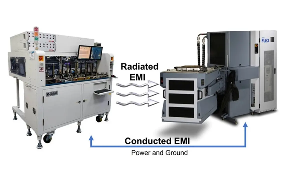
Radiated emission propagates through the air, conducted one - via the wires or via any other conductor (such as metal parts of equipment). You can't have one without the other - any voltage or current generates fields, and any field generates voltages and currents in conductors - after all, this how antennas work. The dealing with these two types of emission is quite different.

Radiated emission is greatly reduced with the distance from the source - for the curious of us, it follows inverse square law. Double the distance from the source and the field drops four times. Practically, if interference is your concern, it means that you only need to worry about radiated sources located close to where it matters for you.

Conducted emission also diminishes with the distance, but to a much smaller degree - it simply doesn't spread around as the fields do. Higher frequencies diminish much faster due to parasitic capacitance and inductance in wires. Realistically, only signals under 1MHz matter - the rest are greatly attenuated, even if the original signal has higher bandwidth


Which One is Worse - Radiated or Conducted EMI?

Radiated EMI inhabits higher frequencies - from tens of MHz to GHz. It mostly affects wireless communication and semiconductor and product test, as well as metrology in R&D and in medical field. Although in close proximity it can be quite strong, it still doesn't have enough energy to cause device damage due to electrical overstress. Plus, of course, its strength rapidly diminishes with the distance.

Conducted EMI has meaningful spectrum up to ~1MHz (of course it has higher-frequency components too, but their amplitude is relatively small). The danger of conducted emission is that is carried for much longer distances than the radiated one while maintaining its strength, and it has plenty of energy to wreck havoc in operation of equipment, in measurements, and even cause device damage. If one is to put most of resources on suppression of EMI, focusing on conducted emission is a wiser choice. OnFILTER focuses on protection from conducted EMI.


Does Radiated Emission Get Into Your Measurements
of Conducted Emission?

Of course it does - any conductor is an antenna: test leads and cables included. One of the "instant" ways to differentiate between the two is to look at the waveform on an oscilloscope. We know now that the radiated emission has much higher bandwidth than the conducted one. In the screenshot here the sharp spike marked by the red "frame" is clearly too short, having too wide of a spectrum for a valid conducted signal. This short spike is radiation-induced signal on wires by the very signal that caused the conducted ringing. It is prudent to discard such abnormal spikes to avoid "chasing ghosts" and ending up with a wrong filter at the end.


How to "Cancel" Radiated Emission and Measure Only Conducted One

Ample warning: this is not for a metrology "purist" - you can find plenty to argue about in this methodology, however it gets the job done using "good enough" approach. There is simply no other practical way to do otherwise - if you know it, we would like to hear from you.

This approach was utilized in the paper "Practical Aspects of Managing EMI-Caused EOS in IC Handlers and Similar Equipment" presented at the 2021 EOS/ESD Symposium and named "Outstanding Paper" - you can read it in our Library, or here is a direct link to this paper.

Assume you want to measure EMI voltage between the arm of the IC handler and its shuttle (or chassis) using EMI Adapter MSN15. This adapter uses regular test leads - anything else is simply impractical for measuring signals between two random points. These test leads act as receiving antennas, picking up signals from the air. These signals add to true conducted EMI measurements making the results appear much stronger than it really is.

The first step is to connect one of the probes to the chassis and leave the other one floating in the close proximity to the eventual point of measurements - just like it is shown in the figure on the left. What you will see on the screen of your instrument is only the radiated emission picked up by the test leads.

Now connect that floating probe to the point of measurements as shown in the figure on the right. The measurements will show the combined radiated and conducted emission. All you would need to do is to subtract the former from the latter and you will have only conducted emission left.


How Does This "Cancellation" Look Like?

EMI Dissected - Before Filtering

Key Spot - Machine Ground

EMI Dissected - After Filtering

Key Spot - Machine Ground

The figures above are taken from the paper mentioned above. which contains detailed description of measurements and EMI mitigation in the IC handler.  The figure on the left shows radiated and conducted measurements in the IC handler before implementation of GLE04-01 filter; the figure on the right - after its implementation. The data to look at is for "Machine Ground" - the other point is for the reference. The culprit in this task was conducted EMI that causes electrical overstress (EOS) and consequent IC damage; radiated EMI in this case is simply a nuisance. Without "canceling" radiated emission, there would be no way to know that the goal of reduction of conducted EMI between the handler's arm and the chassis ("Machine Ground" in both figures) to bellow the limits of SEMI E.176 has been successfully met.


EMI Adapters for Accurate EMI Measurements

EMI Adapters allow for safe measurements of EMI on live power lines using regular oscilloscope and spectrum analyzer. True balanced input eliminates ground loops, and complete rejection of 50/60Hz AC mains allows for accurate measurements of high-frequency signals.


GLE04-01 Ground EMI Filter for Reduction of EMI inside Equipment

Patented GLE04-01 ground EMI filter is used to block propagation of high-frequency signals inside equipment in ESD ground. Internal strong EMI sources such as servo motors, switched mode power supplies, LED lighting, and others "leak" EMI to ground propagating it everywhere in the equipment, including to sensitive electronics and components. GLE04-01 meets all ESD and safety standards while substantially blocking EMI propagation. The filters are small and light, and easy to install.


Should you have any questions on our filters, their applications, or any other aspect of EMI, call us at +61 2 9757 3590 or drop us a line at sales@bondline.com.au

sales@bondline.com.au

Tel. +61 2 9757 3590